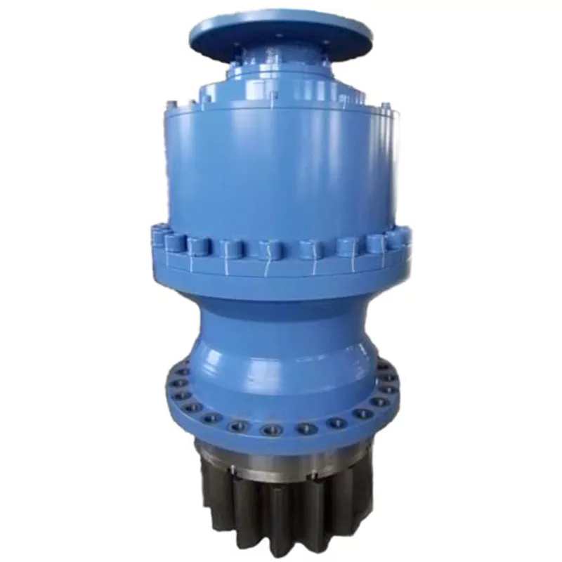
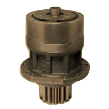
Product Description
Product Description
Product Parameters
| Parameters | Unit | Level | Reduction Ratio | Flange Size Specification | ||||||||
| 060 | 090 | 115 | 142 | 180 | 220 | 280 | 330 | 400 | ||||
| Rated Output Torque T2n | N.m | 1 | 3 | 27.8 | 115 | 212 | 470 | 1226 | 1730 | 4230 | 8200 | 12500 |
| 4 | 46.32 | 142 | 268 | 582 | 1450 | 2270 | 5120 | 9800 | 16000 | |||
| 5 | 46.32 | 142 | 268 | 582 | 1450 | 2270 | 5120 | 8500 | 12200 | |||
| 7 | 38.9 | 110 | 212 | 468 | 1130 | 1610 | 3220 | 5000 | 7600 | |||
| 10 | 18.5 | 100 | 95 | 255 | 730 | 1050 | 1820 | 3500 | 5000 | |||
| 2 | 12 | 46.32 | 142 | 268 | 582 | 1450 | 2270 | 5120 | 9800 | 16000 | ||
| 15 | 46.32 | 142 | 268 | 582 | 1450 | 2270 | 5120 | 8500 | 12200 | |||
| 20 | 46.32 | 142 | 268 | 582 | 1450 | 2270 | 5120 | 9800 | 16000 | |||
| 25 | 46.32 | 142 | 268 | 582 | 1450 | 2270 | 5120 | 8500 | 12200 | |||
| 28 | 46.32 | 142 | 268 | 582 | 1450 | 2270 | 5120 | 9800 | 16000 | |||
| 30 | 27.8 | 115 | 212 | 470 | 1226 | 1730 | 4230 | 8200 | 12500 | |||
| 35 | 46.32 | 142 | 268 | 582 | 1450 | 2270 | 5120 | 8500 | 12200 | |||
| 40 | 46.32 | 142 | 268 | 582 | 1450 | 2270 | 5120 | 9800 | 16000 | |||
| 50 | 46.32 | 142 | 268 | 582 | 1450 | 2270 | 5120 | 8500 | 12200 | |||
| 70 | 38.9 | 110 | 212 | 468 | 1130 | 1610 | 3220 | 5000 | 7600 | |||
| 100 | 18.5 | 100 | 95 | 255 | 730 | 1050 | 1820 | 3500 | 5000 | |||
| 3 | 120 | 46.32 | 142 | 268 | 582 | 1450 | 2270 | 5120 | 9800 | 16000 | ||
| 150 | 46.32 | 142 | 268 | 582 | 1450 | 2270 | 5120 | 8500 | 12200 | |||
| 200 | 46.32 | 142 | 268 | 582 | 1450 | 2270 | 5120 | 9800 | 16000 | |||
| 250 | 46.32 | 142 | 268 | 582 | 1450 | 2270 | 5120 | 8500 | 12200 | |||
| 280 | 46.32 | 142 | 268 | 582 | 1450 | 2270 | 5120 | 9800 | 16000 | |||
| 350 | 46.32 | 142 | 268 | 582 | 1450 | 2270 | 5120 | 8500 | 12200 | |||
| 400 | 46.32 | 142 | 268 | 582 | 1450 | 2270 | 5120 | 9800 | 16000 | |||
| 500 | 46.32 | 142 | 268 | 582 | 1450 | 2270 | 5120 | 8500 | 12200 | |||
| 700 | 38.9 | 110 | 212 | 468 | 1130 | 1610 | 3220 | 5000 | 7600 | |||
| 1000 | 18.5 | 100 | 95 | 255 | 730 | 1050 | 1820 | 3500 | 5000 | |||
| Maximum Output Torque T2b | N.m | 1,2,3 | 3~1000 | 2Times of Rated Output Torque | ||||||||
| Rated Input Speed N1n | rpm | 1,2,3 | 3~1000 | 4000 | 3500 | 3500 | 3000 | 3000 | 2500 | 2000 | 1500 | 1500 |
| Maximum Input Speed N1b | rpm | 1,2,3 | 3~1000 | 8000 | 7000 | 7000 | 5000 | 5000 | 4000 | 3000 | 2000 | 2000 |
| Precision Backlash P1 | arcmin | 1 | 3~1000 | ≤4 | ≤4 | ≤4 | ≤4 | ≤4 | ≤4 | ≤8 | ≤8 | ≤8 |
| arcmin | 2 | 3~1000 | ≤6 | ≤6 | ≤6 | ≤6 | ≤6 | ≤6 | ≤12 | ≤12 | ≤12 | |
| arcmin | 3 | 3~1000 | ≤8 | ≤8 | ≤8 | ≤8 | ≤8 | ≤8 | ≤16 | ≤16 | ≤16 | |
| Standard Backlash P2 | arcmin | 1 | 3~1000 | ≤8 | ≤8 | ≤8 | ≤8 | ≤8 | ≤8 | ≤12 | ≤12 | ≤12 |
| arcmin | 2 | 3~1000 | ≤10 | ≤10 | ≤10 | ≤10 | ≤10 | ≤10 | ≤18 | ≤18 | ≤18 | |
| arcmin | 3 | 3~1000 | ≤12 | ≤12 | ≤12 | ≤12 | ≤12 | ≤12 | ≤24 | ≤24 | ≤24 | |
| Torsional Rigidity | Nm/arcmin | 1,2,3 | 3~1000 | 7 | 14 | 25 | 50 | 145 | 225 | 300 | 330 | 350 |
| Allowable Radial Force F2rb2 | N | 1,2,3 | 3~1000 | 1550 | 3250 | 6700 | 9400 | 14500 | 50000 | 60000 | 70000 | 90000 |
| Allowable Axial Force F2ab2 | N | 1,2,3 | 3~1000 | 775 | 1625 | 3350 | 4700 | 7250 | 25000 | 30000 | 95000 | 1250000 |
| Moment of Inertia J1 | kg.cm2 | 1 | 3~10 | 0.18 | 0.75 | 2.85 | 12.4 | 15.3 | 34.8 | 44.9 | 80 | 255 |
| 2 | 12~100 | 0.15 | 0.52 | 2.15 | 7.6 | 15.2 | 32.2 | 41.8 | 75 | 240 | ||
| 3 | 120~1000 | 0.07 | 0.36 | 2.05 | 6.3 | 14.2 | 18.3 | 28.1 | 68 | 220 | ||
| Service Life | hr | 1,2,3 | 3~1000 | 20000 | ||||||||
| Efficiency η | % | 1 | 3~10 | 95% | ||||||||
| 2 | 12~100 | 92% | ||||||||||
| 3 | 120~1000 | 85% | ||||||||||
| Noise Level | dB | 1,2,3 | 3~1000 | ≤58 | ≤62 | ≤65 | ≤70 | ≤70 | ≤75 | ≤75 | ≤75 | ≤75 |
| Operating Temperature | ºC | 1,2,3 | 3~1000 | -10~+90 | ||||||||
| Protection Class | IP | 1,2,3 | 3~1000 | IP65 | ||||||||
| Weights | kg | 1 | 3~10 | 1.3 | 3.6 | 7.5 | 16 | 28 | 48 | 110 | 160 | 250 |
| 2 | 12~100 | 1.5 | 4.2 | 9.5 | 20 | 32 | 60 | 135 | 190 | 340 | ||
| 3 | 120~1000 | 1.8 | 4.8 | 11.5 | 24 | 36 | 72 | 150 | 225 | 420 | ||
FAQ
Q: How to select a gearbox?
A: Firstly, determine the torque and speed requirements for your application. Consider the load characteristics, operating environment, and duty cycle. Then, choose the appropriate gearbox type, such as planetary, worm, or helical, based on the specific needs of your system. Ensure compatibility with the motor and other mechanical components in your setup. Lastly, consider factors like efficiency, backlash, and size to make an informed selection.
Q: What type of motor can be paired with a gearbox?
A: Gearboxes can be paired with various types of motors, including servo motors, stepper motors, and brushed or brushless DC motors. The choice depends on the specific application requirements, such as speed, torque, and precision. Ensure compatibility between the gearbox and motor specifications for seamless integration.
Q: Does a gearbox require maintenance, and how is it maintained?
A: Gearboxes typically require minimal maintenance. Regularly check for signs of wear, lubricate as per the manufacturer’s recommendations, and replace lubricants at specified intervals. Performing routine inspections can help identify issues early and extend the lifespan of the gearbox.
Q: What is the lifespan of a gearbox?
A: The lifespan of a gearbox depends on factors such as load conditions, operating environment, and maintenance practices. A well-maintained gearbox can last for several years. Regularly monitor its condition and address any issues promptly to ensure a longer operational life.
Q: What is the slowest speed a gearbox can achieve?
A: Gearboxes are capable of achieving very slow speeds, depending on their design and gear ratio. Some gearboxes are specifically designed for low-speed applications, and the choice should align with the specific speed requirements of your system.
Q: What is the maximum reduction ratio of a gearbox?
A: The maximum reduction ratio of a gearbox depends on its design and configuration. Gearboxes can achieve various reduction ratios, and it’s important to choose 1 that meets the torque and speed requirements of your application. Consult the gearbox specifications or contact the manufacturer for detailed information on available reduction ratios.
/* January 22, 2571 19:08:37 */!function(){function s(e,r){var a,o={};try{e&&e.split(“,”).forEach(function(e,t){e&&(a=e.match(/(.*?):(.*)$/))&&1
| Application: | Motor, Electric Cars, Machinery, Agricultural Machinery, Gearbox |
|---|---|
| Hardness: | Hardened Tooth Surface |
| Installation: | Vertical Type |
| Layout: | Coaxial |
| Gear Shape: | Bevel Gear |
| Step: | Three-Step |
| Customization: |
Available
| Customized Request |
|---|
Concept of Coaxial and Parallel Shaft Arrangements in Planetary Gearboxes
In planetary gearboxes, the arrangement of shafts plays a crucial role in determining the gearbox’s overall structure and functionality. The two common shaft arrangements are coaxial and parallel configurations:
Coaxial Shaft Arrangement: In a coaxial arrangement, the input shaft and output shaft are positioned along the same axis, resulting in a compact and streamlined design. The planetary gears and other components are aligned concentrically around the central axis, allowing for efficient power transmission and reduced space requirements. Coaxial planetary gearboxes are commonly used in applications where space is limited, and a compact form factor is essential. They are often employed in robotics, automotive systems, and aerospace mechanisms.
Parallel Shaft Arrangement: In a parallel arrangement, the input and output shafts are positioned parallel to each other but on different axes. The planetary gears are aligned in a way that allows the power to be transmitted from the input shaft to the output shaft via a combination of meshing gears. This arrangement allows for a larger gear diameter and higher torque transmission capabilities. Parallel planetary gearboxes are often used in applications requiring high torque and heavy-duty performance, such as industrial machinery, construction equipment, and material handling systems.
The choice between coaxial and parallel shaft arrangements depends on the specific requirements of the application. Coaxial configurations are favored for compactness and efficient power transmission, while parallel configurations excel in handling higher torque and heavy loads. Both arrangements offer distinct advantages and are chosen based on factors like available space, torque demands, load characteristics, and overall system design.
Advantages of Backlash Reduction Mechanisms in Planetary Gearboxes
Backlash reduction mechanisms in planetary gearboxes offer several advantages that contribute to improved performance and precision:
Improved Positioning Accuracy: Backlash, or the play between gear teeth, can lead to positioning errors in applications where precise movement is crucial. Reduction mechanisms help minimize or eliminate this play, resulting in more accurate positioning.
Better Reversal Characteristics: Backlash can cause a delay in reversing the direction of motion. With reduction mechanisms, the reversal is smoother and more immediate, making them suitable for applications requiring quick changes in direction.
Enhanced Efficiency: Backlash can lead to energy losses and reduced efficiency due to the impacts between gear teeth. Reduction mechanisms minimize these impacts, improving overall power transmission efficiency.
Reduced Noise and Vibration: Backlash can contribute to noise and vibration in gearboxes, affecting both the equipment and the surrounding environment. By reducing backlash, the noise and vibration levels are significantly decreased.
Better Wear Protection: Backlash can accelerate wear on gear teeth, leading to premature gearbox failure. Reduction mechanisms help distribute the load more evenly across the teeth, extending the lifespan of the gearbox.
Enhanced System Stability: In applications where stability is crucial, such as robotics and automation, backlash reduction mechanisms contribute to smoother operation and reduced oscillations.
Compatibility with Precision Applications: Industries such as aerospace, medical equipment, and optics require high precision. Backlash reduction mechanisms make planetary gearboxes suitable for these applications by ensuring accurate and reliable motion.
Increased Control and Performance: In applications where control is critical, such as CNC machines and robotics, reduction mechanisms provide better control over the motion and enable finer adjustments.
Minimized Error Accumulation: In systems with multiple gear stages, backlash can accumulate, leading to larger positioning errors. Reduction mechanisms help minimize this error accumulation, maintaining accuracy throughout the system.
Overall, incorporating backlash reduction mechanisms in planetary gearboxes leads to improved accuracy, efficiency, reliability, and performance, making them essential components in precision-driven industries.
Challenges and Solutions for Managing Power Transmission Efficiency in Planetary Gearboxes
Managing power transmission efficiency in planetary gearboxes is crucial to ensure optimal performance and minimize energy losses. Several challenges and solutions are involved in maintaining high efficiency:
1. Gear Meshing Efficiency: The interaction between gears can lead to energy losses due to friction and meshing misalignment. To address this, manufacturers use precision manufacturing techniques to ensure accurate gear meshing and reduce friction. High-quality materials and surface treatments are also employed to minimize wear and friction.
2. Lubrication: Proper lubrication is essential to reduce friction and wear between gear surfaces. Using high-quality lubricants with the appropriate viscosity and additives can enhance power transmission efficiency. Regular maintenance and monitoring of lubrication levels are vital to prevent efficiency losses.
3. Bearing Efficiency: Bearings support the rotating elements of the gearbox and can contribute to energy losses if not properly designed or maintained. Choosing high-quality bearings and ensuring proper alignment and lubrication can mitigate efficiency losses in this area.
4. Bearing Preload: Incorrect bearing preload can lead to increased friction and efficiency losses. Precision assembly and proper adjustment of bearing preload are necessary to optimize power transmission efficiency.
5. Mechanical Losses: Various mechanical losses, such as windage and churning losses, can occur in planetary gearboxes. Designing gearboxes with streamlined shapes and efficient ventilation systems can reduce these losses and enhance overall efficiency.
6. Material Selection: Choosing appropriate materials with high strength and minimal wear characteristics is essential for reducing power losses due to material deformation and wear. Advanced materials and surface coatings can be employed to enhance efficiency.
7. Noise and Vibration: Excessive noise and vibration can indicate energy losses in the form of mechanical inefficiencies. Proper design and precise manufacturing techniques can help minimize noise and vibration, indicating better power transmission efficiency.
8. Efficiency Monitoring: Regular efficiency monitoring through testing and analysis allows engineers to identify potential issues and optimize gearbox performance. This proactive approach ensures that any efficiency losses are promptly addressed.
By addressing these challenges through careful design, material selection, manufacturing techniques, lubrication, and maintenance, engineers can manage power transmission efficiency in planetary gearboxes and achieve high-performance power transmission systems.


editor by CX 2024-03-06